




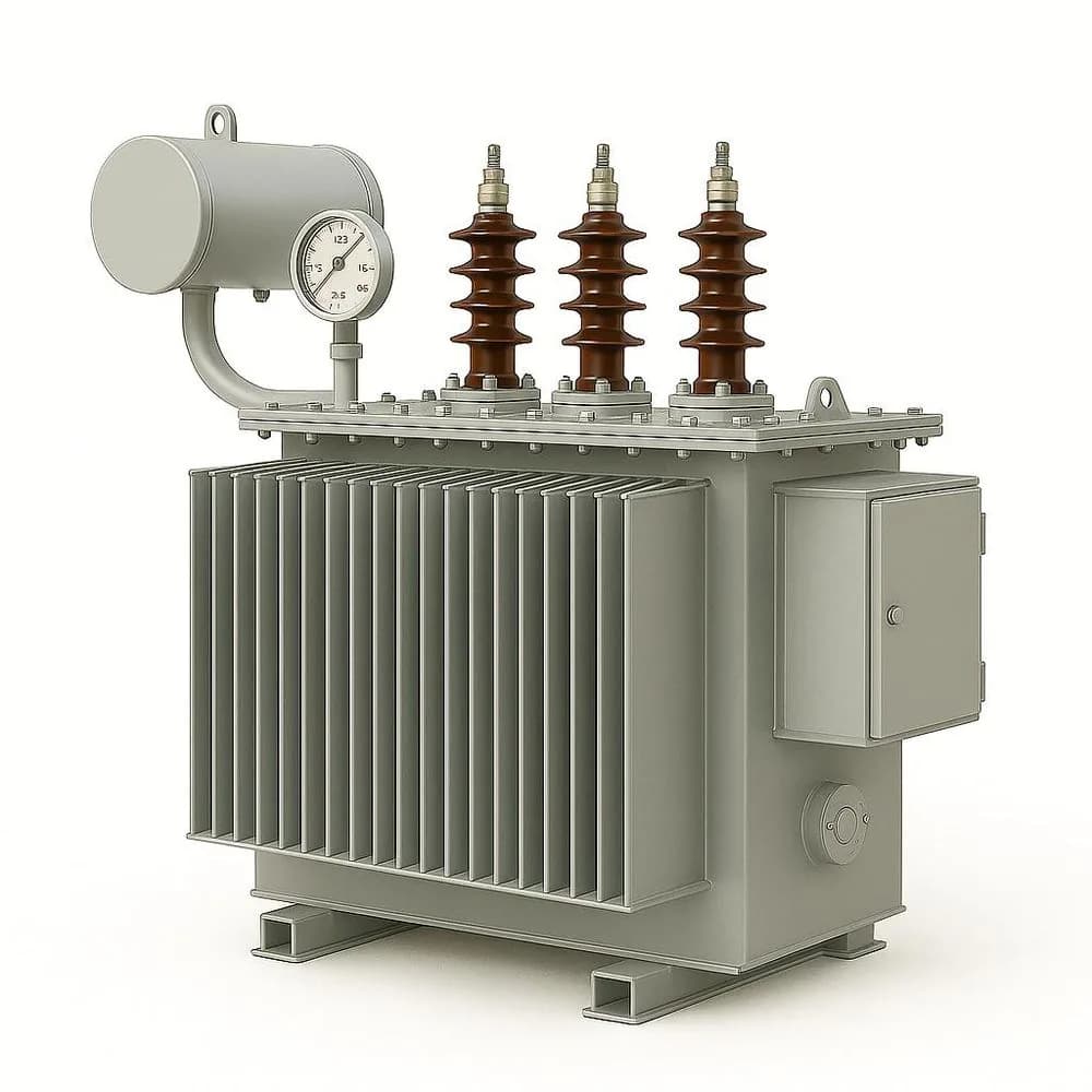
A transformer's rating plate (nameplate), governed by international standard IEC 60076-1, is far more than a simple equipment label. For electrical design engineers, commissioning technicians, and industrial procurement managers, the nameplate provides the definitive electrical parameters required to calculate prospective fault currents, configure protection relays in MV switchgear and LV distribution panels, verify parallel operating conditions, and evaluate lifetime energy losses.
Rated Power, Voltages, and Tapping Range
The primary headline ratings establish the transformer's fundamental operating envelope:
- Rated Power (kVA or MVA)The continuous apparent power the transformer can deliver under rated frequency and voltage without exceeding permissible winding temperature rise limits (typically 65 K for oil, 100 K for Class F dry-type).
- Rated Voltages (HV and LV)The nominal line-to-line voltages (e.g. 20 kV / 400 V or 33 kV / 11 kV).
- Tapping Range & Tap ChangerVoltage adjustment steps on the high-voltage winding, typically ±2 × 2.5% or ±5% via an Off-Circuit Tap Changer (OCTC) or On-Load Tap Changer (OLTC) to compensate for grid voltage variations.
Short-Circuit Impedance Voltage (%Uk / %Z)
Short-circuit impedance voltage (%Uk, often designated as %Z or impedance voltage) is one of the most critical values on the nameplate. It represents the percentage of rated primary voltage required to circulate rated nominal current through the primary winding when the secondary terminals are short-circuited at reference temperature.
The impedance percentage directly determines three vital engineering factors:
- Prospective Short-Circuit CurrentThe maximum symmetrical fault current on the secondary busbar is inversely proportional to %Uk: Isc = In / (%Uk / 100). For example, a 1000 kVA 400 V transformer with a 6% Uk generates a secondary prospective fault current of approximately 24 kA.
- Voltage Regulation under LoadA higher %Uk causes a larger internal voltage drop under heavy lagging power factor loads, requiring closer tap setting management.
- Parallel Load SharingWhen two transformers operate in parallel, their load sharing is inversely proportional to their short-circuit impedances. Transformers with unequal %Uk values will share load disproportionately, risking overload on the unit with lower impedance.
Vector Groups and Phase Displacement (Dyn11, YNd11, Yyn0)
The vector group code defines the winding connection topology (Delta, Wye/Star, or Zigzag) and the angular phase displacement between the primary and secondary line-to-line voltage vectors, expressed in clock face notation (where 1 hour represents a 30° phase lag):
- First Capital Letter (Primary Winding)D = Delta, Y = Wye/Star, Z = Zigzag, N = Neutral brought out to a terminal.
- Second Lowercase Letter (Secondary Winding)d = delta, y = wye/star, z = zigzag, n = neutral brought out to a terminal.
- Clock Number (Phase Angle)11 indicates that the LV voltage vector lags the HV vector by 330° (or leads by 30°). 0 indicates zero phase displacement (0°).
The Dyn11 vector group is the international standard configuration for secondary distribution transformers (oil-immersed and cast-resin dry-type) for three key reasons: the Delta HV winding traps 3rd harmonic currents preventing them from flowing into the upstream grid; the neutral terminal (n) on the Star LV side provides a stable ground reference and 230 V phase-to-neutral supply for single-phase loads; and it handles unbalanced neutral loading efficiently without magnetic core saturation.
Rules for Operating Transformers in Parallel
Mandatory Conditions for Parallel Operation
Never connect transformer secondaries in parallel without verifying all four criteria:
- Identical Vector Group and Phase Angle: Paralleling a Dyn11 with a Yyn0 or Dyn5 creates a 30° or 180° phase difference, resulting in an immediate catastrophic phase-to-phase short-circuit.
- Equal Voltage Ratios and Tap Positions: Must be matched to prevent large circulating currents between windings even at zero external load.
- Matching Percentage Impedances (%Uk): Impedance values must match within ±10% tolerance so that load divides proportionally to each transformer's kVA rating.
- Capacity Ratio within 3:1: The kVA rating of the largest transformer should not exceed three times the rating of the smallest unit.
Transformer Losses: No-Load Core Losses (P0) vs. Load Copper Losses (Pk)
Transformer losses are divided into two distinct components that dictate operating efficiency and total cost of ownership (TCO):
- No-Load Losses (P0 / Core Losses)Constant power dissipated in the magnetic steel core due to hysteresis and eddy currents whenever the transformer is energized, regardless of connected load. Governed by magnetic core grade (grain-oriented silicon steel or amorphous metal).
- Load Losses (Pk / Copper Losses)Variable power dissipated in the primary and secondary winding conductors due to I²R resistance and stray eddy currents, proportional to the square of the load current. Measured at rated current and reference temperature (75°C for liquid, 120°C for dry-type).
Under the European Union Ecodesign Regulation (Commission Regulation (EU) 2019/1783, Tier 2), strict maximum threshold limits are enforced for both P0 and Pk on all medium power transformers placed on the EU market, drastically reducing lifetime carbon emissions and electricity waste.
Cooling Designations (IEC 60076-2)
Cooling codes describe the internal insulating medium and external circulation mechanism:
- ONAN (Oil Natural Air Natural)Standard self-cooled oil-immersed transformer utilizing natural thermosiphon oil convection and ambient air circulation across corrugated tank walls or radiators.
- ONAF (Oil Natural Air Forced)Fan-assisted cooling that increases transformer continuous rating by 20% to 33% during peak demand periods.
- AN / AF (Air Natural / Air Forced)Standard natural convection cooling (AN) or fan-boosted cooling (AF) for cast-resin dry-type transformers.
Nameplate Parameter Interpretation Table
| Nameplate Parameter | Typical Specification | Engineering Significance |
|---|---|---|
| Rated Power (Sr) | 100 kVA to 3150 kVA | Maximum continuous apparent power delivery without thermal overload |
| Voltage Ratio (Ur) | 20,000 V / 400 V | Primary and secondary line-to-line open-circuit voltage ratio |
| Short-Circuit Impedance (%Uk) | 4.0% to 6.0% | Governs short-circuit fault current, voltage drop, and parallel load sharing |
| Vector Group | Dyn11 | Winding topology, neutral availability, harmonic blocking, and paralleling compatibility |
| No-Load Losses (P0) | Watts (W) per Ecodesign Tier 2 | Constant continuous iron core power dissipation 24/7/365 |
| Load Losses (Pk) | Watts (W) at 75°C / 120°C | Winding copper dissipation at 100% full load current |
| Cooling Method | ONAN / ONAF / AN / AF | Specifies thermal dissipation mechanism and fan-forced upgrade rating |
| Insulation Class / Temp Rise | Class A (60/65 K) or Class F (100 K) | Permissible winding temperature rise above 40°C maximum ambient |
| Basic Impulse Level (BIL) | 95 kV / 125 kV / 170 kV | Lightning impulse withstand voltage rating for surge protection coordination |
Procurement and Specification Checklist
Transformer Specification Checklist for RFQs
When requesting a transformer quotation, ensure your technical schedule defines:
- Rated capacity (kVA or MVA) and primary/secondary operating voltages.
- Vector group requirement (e.g. Dyn11 for 4-wire secondary distribution).
- Specified short-circuit impedance (%Uk) and tolerance limits.
- Loss evaluation capitalisation factors or maximum allowable P0 and Pk values (e.g. EU Ecodesign Tier 2 compliance).
- Cooling type (ONAN oil-immersed vs. AN dry-type cast resin) and installation environment (indoor room, compact kiosk, or outdoor yard).
- Tap changer type (Off-circuit OCTC ±2 × 2.5% vs. On-load OLTC) and accessories (Buchholz relay, oil thermometer, pressure relief device).
Specifying or replacing a distribution transformer for your substation project? Explore Imperium's power and distribution transformers, or consult our technical consulting team to review your single-line diagram and loss requirements. Contact us on our quotation request page.
Technical References
- IEC 60076-1Power transformers – Part 1: General. IEC Webstore Standard
- IEC 60076-5Power transformers – Part 5: Ability to withstand short circuit.
- Commission Regulation (EU) 2019/1783 amending Regulation (EU) No 548/2014 on ecodesign requirements for small, medium and large power transformers (Tier 2).